DIGITAL TERRAIN MODEL

VESTRA DTM for AutoCAD provides you with calculation and analysis functions for a wide range of areas, including contour lines, slope aspects, intersections, excavation constructions, landfill surveillance, sloped areas, volume calculations and height zone calculations. Whether you need to perform routine work or complex tasks, you can work faster and more economically with VESTRA.
Characteristics
- The application calculates a digital terrain model with a high degree of performance and precision; even very large datasets (of different origins) pose no problem whatsoever.
- The calculation of the digital terrain model is based on Delaunay triangulation.
- All 3D lines and curves that are selected for calculation are automatically recognized as break lines. A graphical error analysis checks the output data.
- The application can be operated intuitively using wizards. It doesn‘t matter whether you are calculating contour lines and profiles, intersecting models and determining volumes or creating depth zones.
Characteristics - Details
Model creation
- The application can be used in multiple specialist areas, as the data required in order to calculate the DTM can be taken from the DWG
- Alternatively, in the case of large data quantities such as aerial survey data, terrain models can also be calculated directly from an ASCII file, without having to import the data into the AutoCAD platform first.
- DTMs are created in accordance with the Delaunay procedure, calculation occurs as a DTM triangular network with the automatic incorporation of break lines; any number of inside and outside boundaries is possible, thanks to prior data selection in the DWG.
- 3D lines and curves are automatically recognized as break lines. Every break line side becomes the edge of a triangle.
- Graphical error analysis and reporting allow break line intersections, points with the same position but different heights and other error sources to be quickly located
- DTM triangles are stored in a separate file (*.dgm) so that several terrain statuses can be managed and loaded as required; the graphical display can be based on layers or the Civil Object Model.
- Optional: adoption of original point names and reports in triangulation (e.g. as calculation evidence)
- An optimized algorithm allows point volumes of any size to be processed with outstanding performance.
- Various functions are available for incorporating points into the model or deleting existing points.
- The function for importing and exporting various models supports an optimum project structure.
- Triangle geometries are adopted as a VESTRA DTM without recalculation.
- Surfaces can be imported from REB 22.013, GAEB 22.114 and GAEB 20.404, and can be exported from prisms to REB 22.013 and GAEB 22.114.
Properties
- Triangle edges can be subsequently swapped.
- Calculated triangles can be classified by color, for instance as roads, terrain, slopes or water.
- DTM height change: the imported or calculated DTM can be raised or lowered.
- Additional points and break lines can be incorporated into or removed from a DTM.
- Points can be output from an imported DTM with or without point numbers, break lines, and inside and outside boundaries. This function is often needed when a customer supplies a DTM without the corresponding topography.
- Triangle lists or Excel spreadsheets can be output.
Analyses and profiles
- Contour lines can be calculated in any interval, with individual annotation based on the current model or the calculated prismodial volumes
- Profiles and cross sections for alignments or lines can be created with the support of a wizard; the interval, special stations and distances are freely definable, an intersection at break lines can optionally be included; results are displayed and checked in a separate window.
- The calculated profiles can be saved on any horizons in the cross section database. Additional information regarding an alignment, line, DTM or terrain is displayed.
- Colored slope maps are available for adjustable slope classes, while slope arrows and high/low points aid presentation.
- A list of sloped and projected areas can be output, optionally with triangle or focal point coordinates.
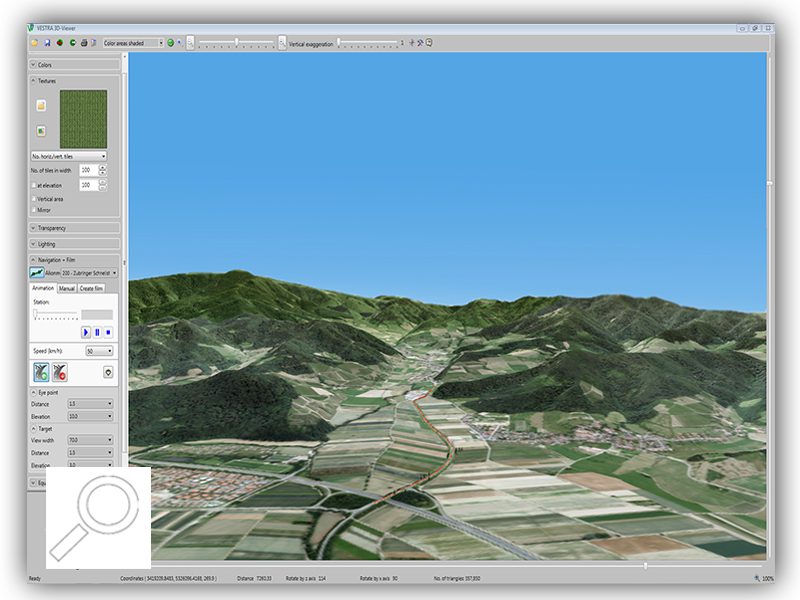
Visualization
- Terrain visualization as 3D view for checking calculations; viewpoint, lighting and type of display can be defined as required.
Model intersection and quantity determination
- Model intersection and quantity determination
- Two digital terrain models can be automatically intersected to form a joint new model without user intervention.
- The quantity calculation wizard offers various calculation variants: either between two models, between a model and a reference horizon or as water volumes between a model and a fill level. The results are the colored display and the prism calculation report.
- Calculated cut and fill areas can be output and saved as separate DTM models.
- A quantity calculation that has been performed can be saved and loaded at a later stage.
- Triangles can be annotated with triangle numbers and point numbers for independent verification.
Differential DTM
- Automatic creation of depth/height zones by means of the creation of differential terrain models
- Differences can be output as a contour line.
Constructions
- Generation of a point raster (e.g. 5m x 5m) from a loaded DTM; selection section either graphical or using an existing polygon; points saved in a freely definable layers.
- Flexible point constructions based on the intersection of two or three sloped planes with a horizon (NN height)
- Calculation of (excavation) edges based on the slope and the horizon height
- Calculation of excavation edges as intersection lines with the current DTM
- User-defined height formation: the heights of existing points and lines can be transformed into a sloped area. The sloped area can be defined based on the absolute height, DTM height or slope values. Points located within this level can be selected and are assigned the interpolated height from the previously defined level. This function is excellent for planning the bottom of excavations or landfills.
Special features
- Height assignment of terrain heights from the DTM to points and lines in the database (DWG)
- Soil samples: measured points with relative height specifications (e.g. -0.20 m) and an existing DTM can be used to generate new points that are assigned the difference between the original relative height and the available DTM height as their new height. The plus/minus sign for the relative height can optionally be taken into account
DTM as a list and in Excel
- Output of detailed construction accounting information either in the form of a list or in Excel format: number of triangles, triangle information, maximum and minimum slope, 2D and 3D areas
Display
- Model as triangulation in a separate feature layer or on Civil Object Model
- Triangle information as a window: height, slope, area and edge length